
Black & Decker Li2000 Reverse Engineering
All geared up!
Overview:
The goal of this project was to disassemble a Black & Decker Li2000 motorized screwdriver, measure and model its gearbox, and analyze the mechanics and manufacturing processes behind its components before reassembling it.
The disassembly and analysis of this motorized screwdriver allowed students to apply their knowledge of geometric dimensioning and tolerancing (GD & T), design for manufacturing and assembly (DFMA), and gear trains and develop an understanding of what makes a common household product successful.
A graphical representation of the complete product structure is shown below.
Note that the dotted line above that connects the plastic casing to the ring gear indicates that the ring gear is in fact housed around the interior of the casing (by the collar).
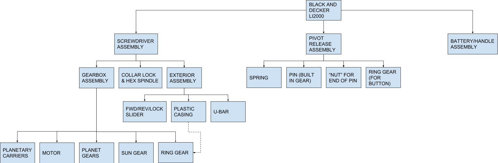
Graphical representation of the motorized screwdriver's product structure
Product Breakdown:
To begin the analysis, the product was first disassembled. An image of an "in real life" exploded view of the components is pictured below. We did not disassemble the lithium battery due to safety risks and the requirement demonstration a working reassembled product. With all of the components laid out, we were able to measure the assorted gears of the gear train and assess the safety mechanisms built into the product. This information allowed us to draw up a simplified assembly of the gear train and animate a 3D model of the gear train.
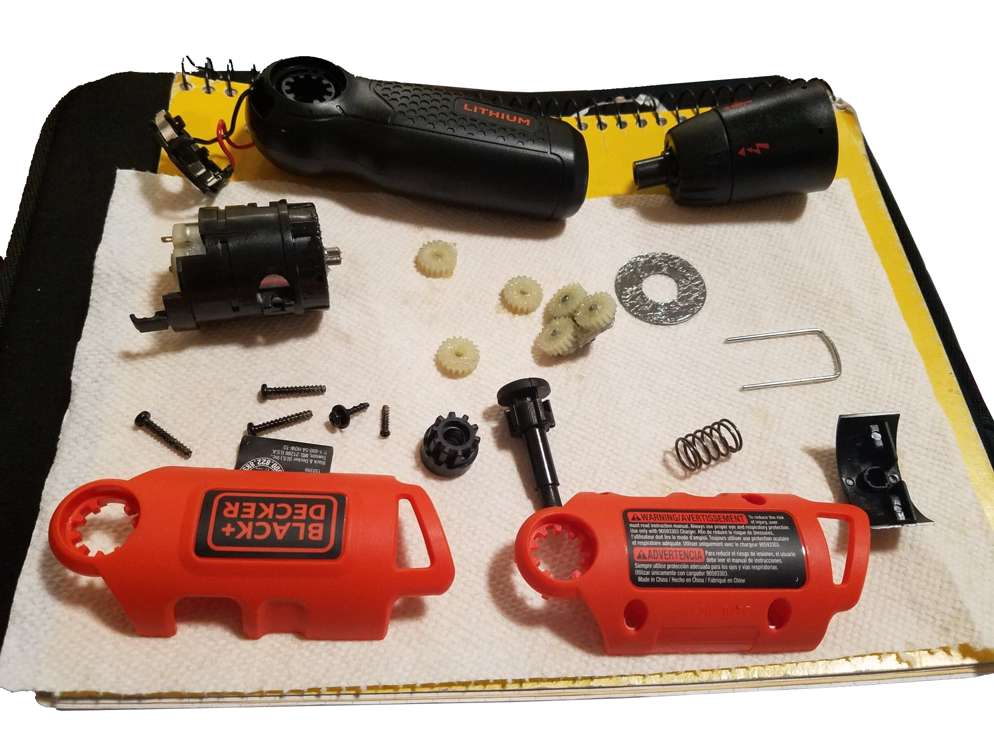
Image of a disassembled product
Engineering drawings of the simplified gear box assembly and its components are as follows:
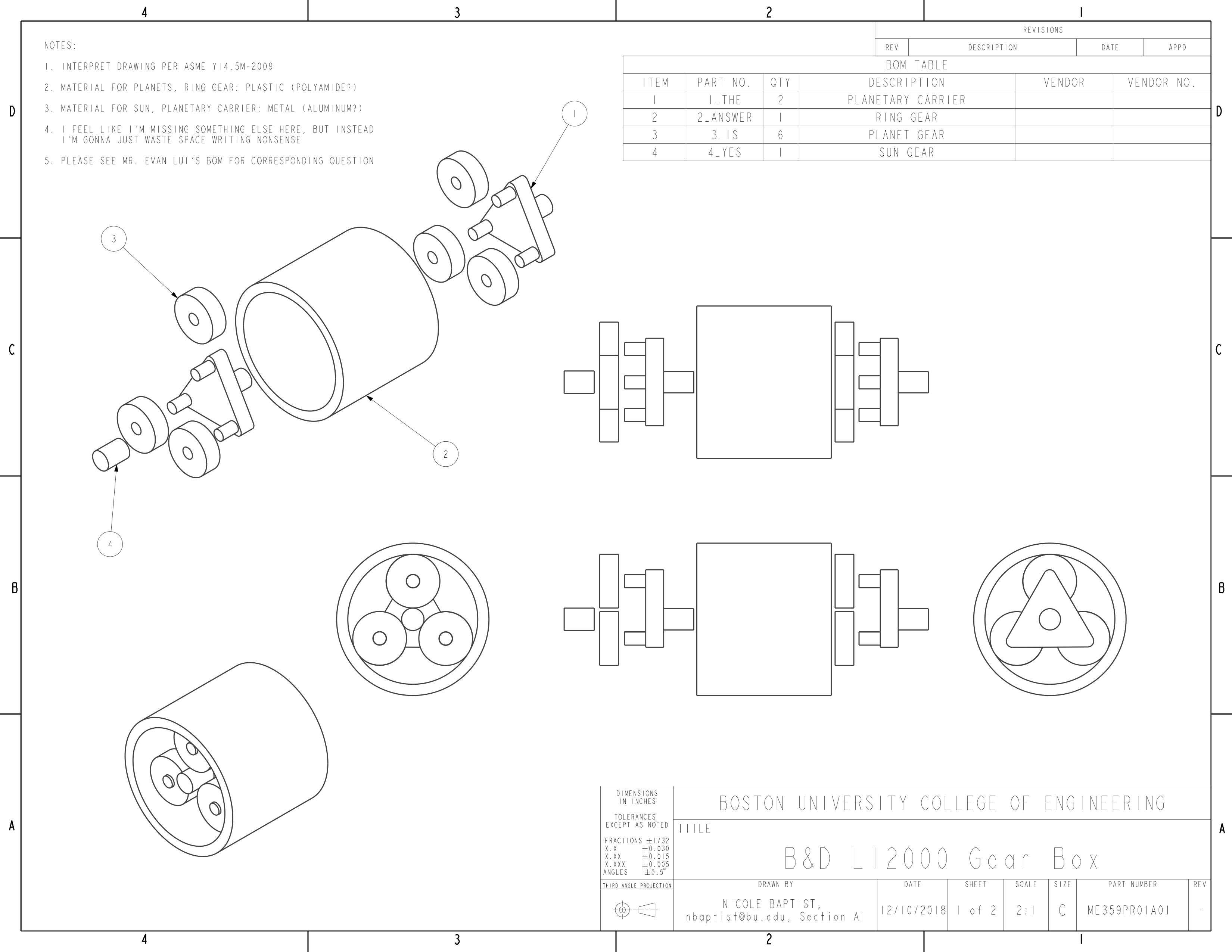
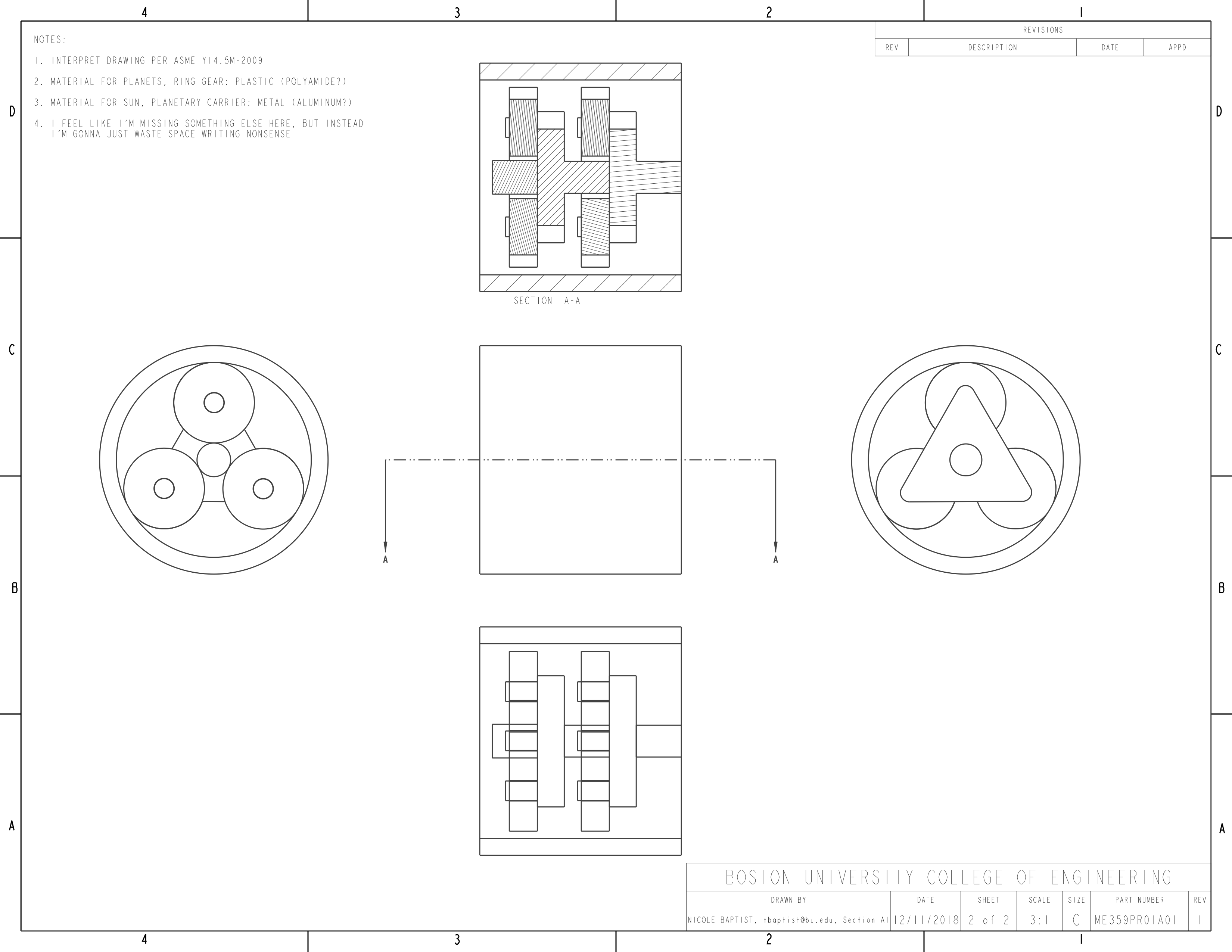
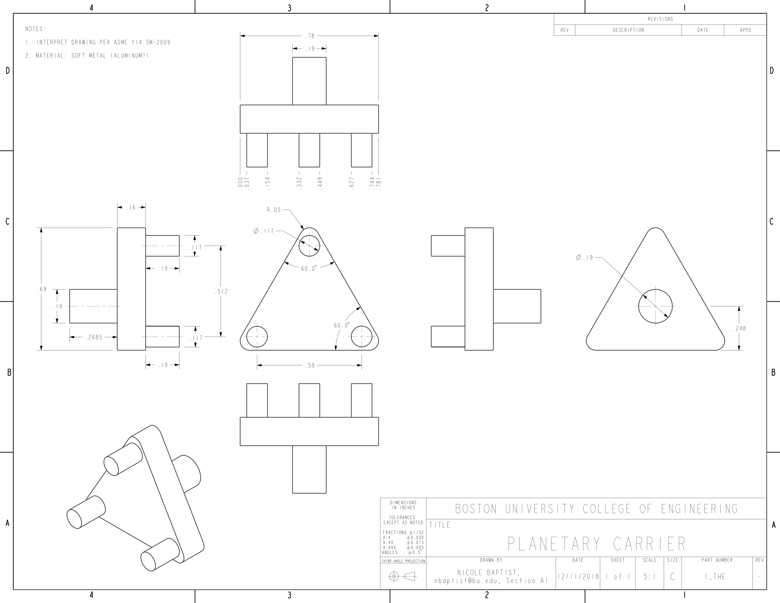
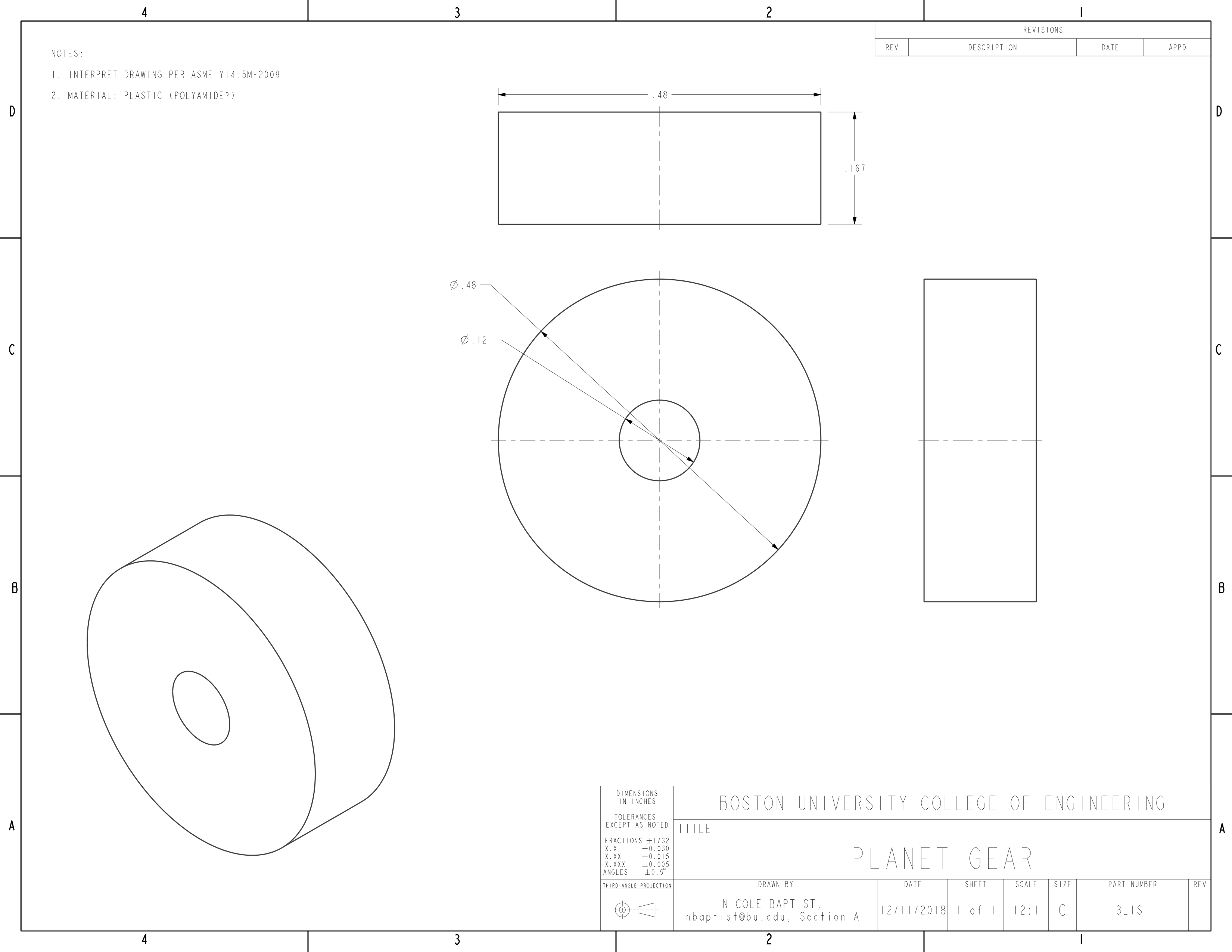
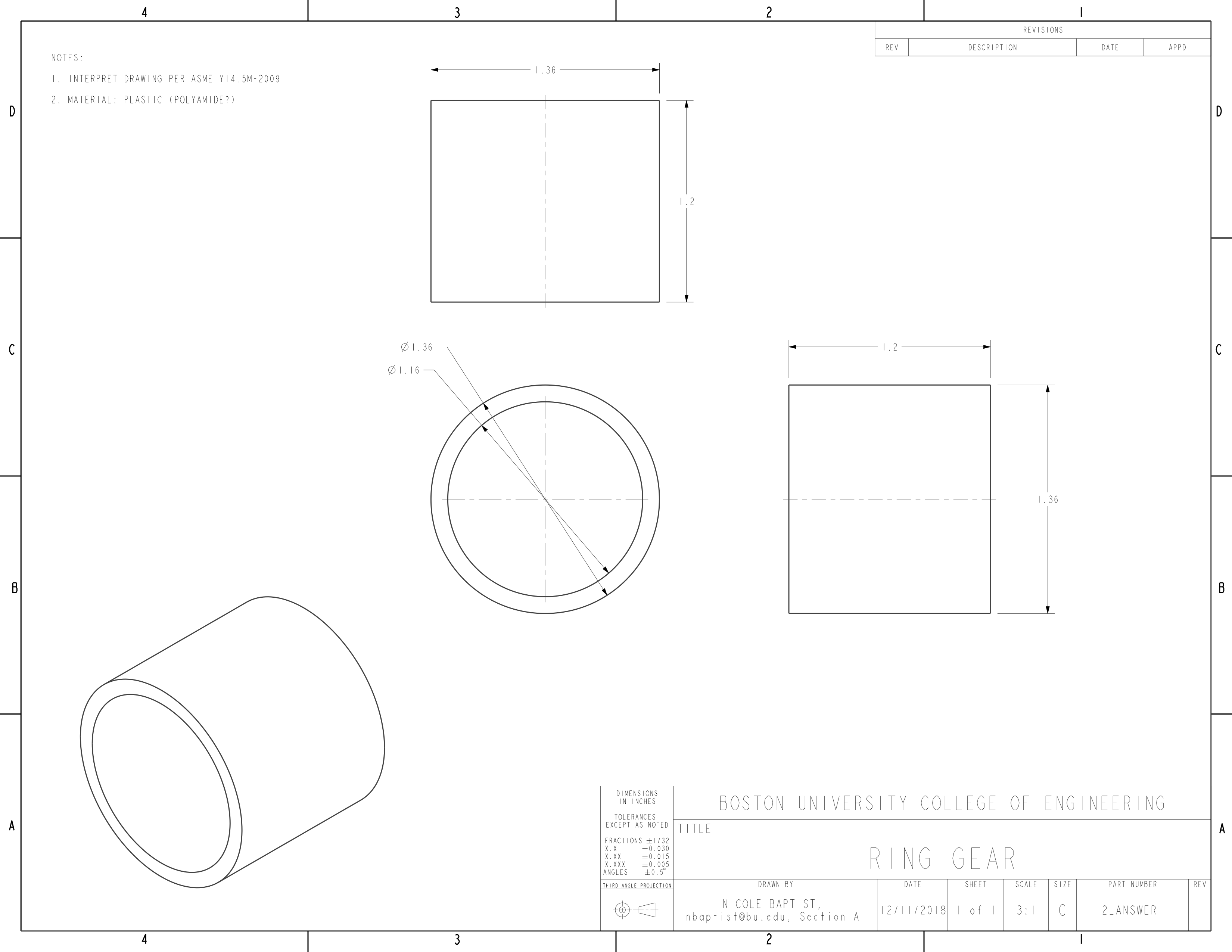

(Please click on an image to enlarge it)
Gearbox Analysis:
In order to begin modelling the gear train, an analysis of the gearbox is required. The measurements used to model the gears from the previous section were used in conjunction with the number of teeth (N) recorded for each component to make accurate 3D models for the animation. The following calculations of the gear box’s components’ pitch diameters (PD) and the gear box’s gear ratio (GR) are shown below:
$$\textbf{Pitch Diameters } (in)\\$$
$$sun: \begin{matrix}
\textup{OD}=0.227\textup{"} &\to 0.227-\frac{0.227-0.173}{2} &\to 0.2 = PD_{sun} \\
\textup{OD}=0.173\textup{"} & &
\end{matrix}$$
$$planet: \begin{matrix}
\textup{OD}=0.54\textup{"} &\to 0.54-\frac{0.54-0.42}{2} &\to 0.48 = PD_{planet} \\
\textup{OD}=0.42\textup{"} & &
\end{matrix}$$
$$ring: \begin{matrix}
\textup{OD}=1.22\textup{"} &\to 1.22-\frac{1.22-1.1}{2} &\to 1.16 = PD_{ring} \\
\textup{OD}=1.1\textup{"} & &
\end{matrix}$$
$$PD_{sun} + PD_{ring} = 0.2 + 1.16 = 1.36 = PD_{carrier}$$
$$N_{sun} = 6 \qquad N_{ring} = 48 \qquad N_{carrier} = 6 + 48 = 54$$ $$GR_{1} = \frac{N_{out}}{N_{in}} = \frac{N_{pc}}{N_{sun}} = \frac{54}{6} = 9$$ $$GR_{2} = \frac{N_{out}}{{N_{in}}^{*}} = \frac{N_{pc}}{N_{sun}} = \frac{54}{6} = 9$$
* ~ sun since the back of the planetary carrier (PC) can be assumed as the second sun sharing an axis with the carrier
For the epicyclic gear train, the gear ratio is:
$$\begin{align*}
GR_{total} &= GR_{1} \times GR_{2}\\
&= 9 \times 9\\
&= 81:1
\end{align*}$$
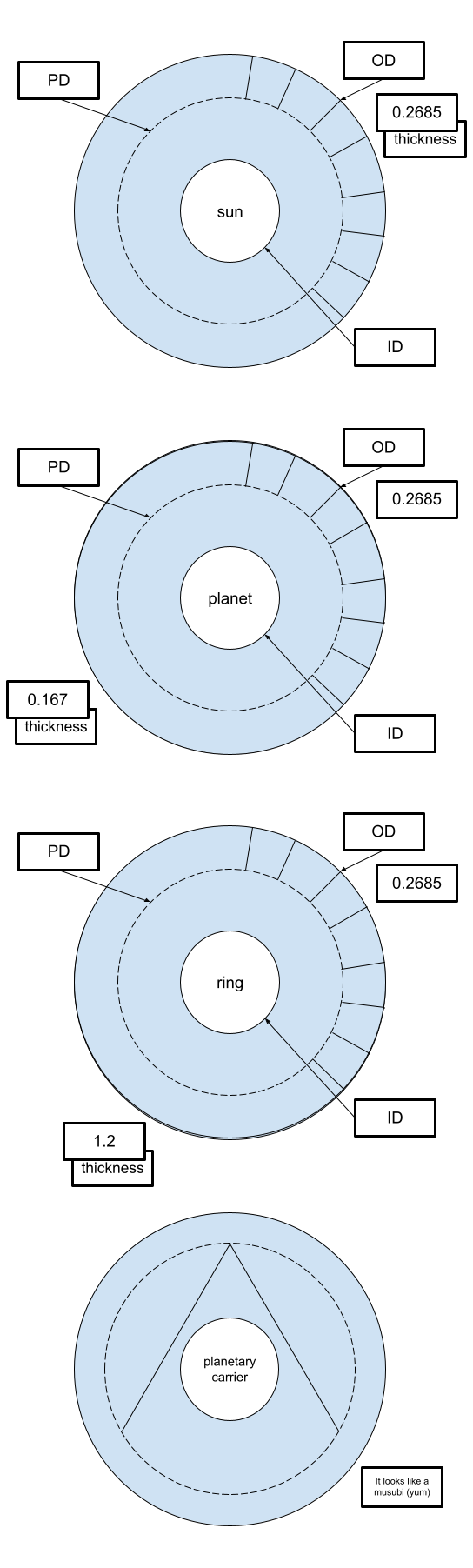
Note: OD = outer diameter, ID = inner diameter, PD = pitch diameter, N = number of teeth on gear, GR = gear ratio
It is noted that Black and Decker likely chose to use an epicyclic gear train since such a formation provides a greater power density than that of a parallel axis gear train. (The chuck might not spin as fast as the motor due to the number of gears present, but more force is necessary to interfere with its rotation, as the epicyclic formation is designed to the increase the output torque.) This is a key feature of power tools, as their action must be consistent and reliable, regardless of the situation they are applied in.
Design for Manufacturability and Assembly (DFMA):
Some important decisions made when designing a product include those which account for the manufacturability and assembly capabilities of the product to ensure that they are feasible to produce parts for, quick to assemble, and constructed simply enough to reduce the possibility of a recall due to manufacturing or assembly errors.
Six mistake-proofing principles to help reduce these errors are elimination, replacement, prevention, facilitation, detection, and mitigation.
While it is difficult to identify elimination and replacement methods applied to the Li2000 screwdriver due to the nature of the project, some noticeable DFMAs are as follows:
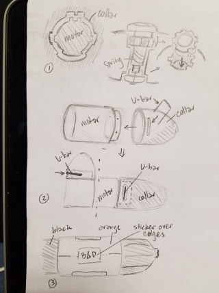
(1) Prevention (motor-collar connection, pivot release button) The unique geometry of the motor and the lip of the collar that it fits into only allows the two to be assembled in a specific orientation so that it is impossible for the gears to not line up. Similarly, the tooth widths of the collar and pivot release mechanism only allow the pin and end button to be inserted in a specific way such that the gears only rotate into specific positions.
(2) Elimination (U-bar) The use of a u-bar to hold the motor and collar together instead of screws, snap fits, adhesives, etc. made it easy for the user to access the gear box without having to worry about damaging the exterior, and the notch and holes that the bar fit into kept the components together well.
(3) Facilitation (Stickers) The stickers that overlapped the edges of the screwdriver ensured that the two halves of the orange housing lined up. The color coding of the components as well (orange vs black) not only served as aesthetic appeal to customers, but also helped the user to reassemble the pieces, were they to take the screwdriver apart.
Other Mechanical Elements:
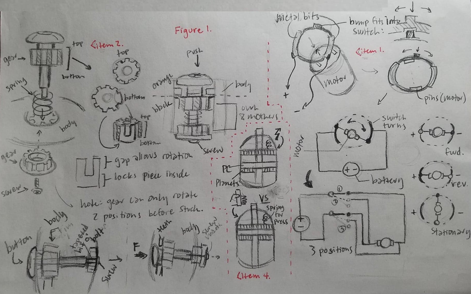
For reference diagrams please see the figure below
Forward/reverse switch (item 1): The switch is composed of two separate metal strips, each connected to one terminal of the battery, on a ring that rotates to change the contact points between the battery and the motor. There are three positions possible. The first position is when the switch is left in the center so that neither of the two metal strips touch the pins protruding from the motor (facing the handle, away from the gear box). This switch position creates an open circuit, so no current flows from the battery to the motor, and thus the spindle is stationary (no rotation). The second position (when the positive and negative terminals of the motor and the battery match up) allows current to flow from the battery through the DC motor so that the motor rotates “forward” (clockwise). The third position reverses these connections so that the current flows in the opposite direction through the motor. This changes the rotational direction of the motor (due to the reversed charges within the coils) so that the motor spins in the reverse direction (counterclockwise).
Handle pivot lock (item 2): The handle pivot lock works by inserting the pin and spring into the joint above the handle and connecting it to the corresponding gear on the opposite side of the joint with a screw (note that both gears can only fit into the joint one way). Once secured, pushing the pin into the housing forces the bottom gear slightly out, allowing the two to turn together. Despite the fact that the teeth cover the entire circumference of the gear, the handle is only able to rotate to three different positions (90º, 135º, and 180º), as the u-shaped tooth on each gear and the geometry of the handle only allow for rotation in one direction.
Power/manual option (item 4*): The power/manual “switch” on the collar forcefully stops the rotation of the gears and motor by applying pressure with a plate attached to a spring, as seen in
Takeaways and Conclusion:
This project was great in that it gave us the chance to disassemble a relatively simple product and figure out how it worked. However, unlike in the Introduction to Engineering Design class, we were able to apply the knowledge acquired through the year. We were also much more familiar with the functions of the product (especially after all of that gear train work, yeesh).
I’d have to say the best part of the project was coming up with the part numbers.
Please see Mr. Evan Lui’s part numbers for the corresponding question.